


Hello all, welcome to another Arduino Sensor Tutorial, in this Blog, we will learn how to wire and code MPU6050 which is a 6 axis Accelerometer, with our Arduino Board, in detail, so follow till end!
Supplies for mpu6050:
Hardware
Software
( Thanks UTSOURCE to offer electronic components for my projects )
Step 1: Watch the Video Tutorial
MPU6050 is the world’s first integrated 6-axis Motion Tracking device that combines a 3-axis gyroscope, 3-axis accelerometer, and a Digital Motion Processor™ (DMP). A
ll in a small 4x4x0.9mm package which is theIntegrated Circuit in Middle. It is based on I2C communication protocol. Rather than discussing the specifics, refer the Datasheet of MPU 6050.
Step 3: Hardware
MPU6050 comes in a Module form, with 8 pins, but don’t worry.
we will use only 4 important pins and it will be sufficient to integrate with our Arduino Board.
So we have VCC, ground, which takes any input from 2v to 5v. Since this board has a voltage regulator on board and thus supports 3.3v logic high and 5v logic high.
Next we have few complimentary resistors and capacitors in SMD package. It is the most important PART the MPU6050 IC. Which is a MEMS or say micro electro mechanical system, which changes voltage depending on change in axis position.
This IC also has SCL SDA.
Which are I2C pins and XDA and XCL which are auxiliary Serial pins. we won’t use them with Arduino for this tutorial. We have AD0 which is address select between Auxiliary and Primary ports. Lastly we have INT interrupt pin,
connections for our Arduino UNO and NANO are as following:
VCC – 5v
GND – GND
SCL – A5
SDA – A4
(only SDA and SCL pins change for other Arduino boards.)
And that’s all for connection for mpu6050
( find all the components at UTSOURCE )
Step 4: Install Libraries
Before we start Coding, we will need a library called as Arduino MPU-6050 by jarzebski,
also we will need Wire Library, which is inbuilt, so we will just install MPU – 6050 Library.
here is the link to MPU6050 Library.
To install a new library into your Arduino IDE you can use the Library Manager.
- Open the IDE and click to the “Sketch” menu and then Include Library > select the option to “Add .ZIP Library”.
- Navigate to the .zip file’s location and open it.
for more information on importing, refer https://www.arduino.cc/en/guide/libraries
Step 5: Open Gyroscope Example.
once the MPU-6050 library is added to Arduino IDE, we have quite a list of examples to choose from, like
-
MPU6050_accel_pitch_roll
-
MPU6050_accel_simple
-
MPU6050_free_fall
-
MPU6050_gyro_pitch_roll_yaw
-
MPU6050_gyro_simple
-
MPU6050_motion
-
MPU6050_temperature
we need to start slow to understand the Library and Basics, so lets start with MPU6050_gyro_simpleexample.
(did you know MPU6050 has a Tempreature Sensor as well, but not very accurate one so we didn’t discuss it here!)
Step 6: Understand the code


Basically in this example, we will see if our sensor is working so we will display the sensor data on serial monitor.
-
So we begin the serial monitor in setup part.
Serial.begin(115200);
- Execute the sensor test sequence in this While Loop,
while(!mpu.begin(MPU6050_SCALE_2000DPS, MPU6050_RANGE_2G))
{    Serial.println("Could not find a valid MPU6050 sensor, check wiring!");
delay(500);
}
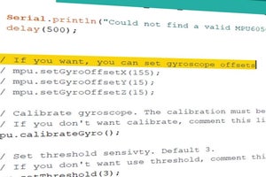
Sometimes we are making a project, and have to set our sensor in a specific orientation, we need offsets, we don’t need it for this tutorial,
- but to change offset, simply un-comment these lines.
// mpu.setGyroOffsetX(155);
// mpu.setGyroOffsetY(15);
// mpu.setGyroOffsetZ(15);
( uncomment by removing "//" )
- there is a calibration line, which will virtually set our sensor flat.
// Calibrate gyroscope. The calibration must be at rest.
// If you don't want calibrate, comment this line.
mpu.calibrateGyro();
Remember offset and calibration are two different things, offset will give you defined calibration, for example, you can mount this sensor at weird angle and yet it will act as reference point for zero.
- Next we have sensitivity, which at default is 3.
// Set threshold sensivty. Default 3.
// If you don't want use threshold, comment this line or set 0.
mpu.setThreshold(3);
-
In check loop section, basic hardware checking is done.
I highly suggest to leave this loop as it is.
- in loop section, which is most important part of this entire code, that is getting the values from our sensor. First we need to call the values, using mpu.readRawGyro or mpu.readNormalizeGyro. now the concept of raw and normalized is such that raw are basically numbers and normalized values are values which go through filters and calculations. or you can say, processed data.
I am raw html block.
Click edit button to change this html
We have 3 axis, called as x y and z, which can be called using variable name which we set as rawGyro. Followed by axis name,to make a project, we will need these 3 values of x,y and z using this variablename.axis command.
I am raw html block.
Click edit button to change this html
- atlast, to view the values at comfortable speed, lets increase the delay from 10 to 1000
delay(10);
}
since our example code is ready and we understand what we did in code, its time to upload the code and view results.


when the upload is done open up the serial monitor and observe output
Don’t forget to match the serial port with the baud rate we defined in start of code which is 115200
If our wiring and hardware is proper, we should get values of each axis on Serial port for both Raw and Normalized gyroscopic change in sensor.
I am raw html block.
Click edit button to change this html
here is the logs of what we got on Serial Port.
Step 8: What Next?

Now this was the basic part, we can also use our sensor to control a model Paper plane using processing software, but that’s a tutorial for next blog.
Subscribe and hit the notification button, to not miss any future blog/ video from Mission Critical.
Also give this post thumps up and share it with your friends. Until the next one, GoodBye!


")


4 Comments
This line is in pink: while(!mpu.begin(MPU6050_SCALE_2000DPS, MPU6050_RANGE_2G))
at the very bottom this is
exit status 1
‘class MPU6050’ has no member named ‘begin’
This is the error code:
Arduino: 1.8.13 (Windows 10), Board: “Arduino Nano, ATmega328P (Old Bootloader)”
C:\Users\*****\AppData\Local\Temp\Temp1_Arduino-MPU6050-master.zip\Arduino-MPU6050-master\MPU6050_accel_simple\MPU6050_accel_simple.ino: In function ‘void setup()’:
MPU6050_accel_simple:20:14: error: ‘class MPU6050’ has no member named ‘begin’
while(!mpu.begin(MPU6050_SCALE_2000DPS, MPU6050_RANGE_2G))
^~~~~
MPU6050_accel_simple:20:20: error: ‘MPU6050_SCALE_2000DPS’ was not declared in this scope
while(!mpu.begin(MPU6050_SCALE_2000DPS, MPU6050_RANGE_2G))
^~~~~~~~~~~~~~~~~~~~~
C:\Users\Ianka\AppData\Local\Temp\Temp1_Arduino-MPU6050-master.zip\Arduino-MPU6050-master\MPU6050_accel_simple\MPU6050_accel_simple.ino:20:20: note: suggested alternative: ‘MPU6050_RA_FF_DUR’
while(!mpu.begin(MPU6050_SCALE_2000DPS, MPU6050_RANGE_2G))
^~~~~~~~~~~~~~~~~~~~~
MPU6050_RA_FF_DUR
MPU6050_accel_simple:20:43: error: ‘MPU6050_RANGE_2G’ was not declared in this scope
while(!mpu.begin(MPU6050_SCALE_2000DPS, MPU6050_RANGE_2G))
^~~~~~~~~~~~~~~~
C:\Users\Ianka\AppData\Local\Temp\Temp1_Arduino-MPU6050-master.zip\Arduino-MPU6050-master\MPU6050_accel_simple\MPU6050_accel_simple.ino:20:43: note: suggested alternative: ‘MPU6050_RA_FF_DUR’
while(!mpu.begin(MPU6050_SCALE_2000DPS, MPU6050_RANGE_2G))
^~~~~~~~~~~~~~~~
MPU6050_RA_FF_DUR
C:\Users\Ianka\AppData\Local\Temp\Temp1_Arduino-MPU6050-master.zip\Arduino-MPU6050-master\MPU6050_accel_simple\MPU6050_accel_simple.ino: In function ‘void checkSettings()’:
MPU6050_accel_simple:45:10: error: ‘MPU6050_CLOCK_EXTERNAL_19MHZ’ was not declared in this scope
case MPU6050_CLOCK_EXTERNAL_19MHZ: Serial.println(“PLL with external 19.2MHz reference”); break;
^~~~~~~~~~~~~~~~~~~~~~~~~~~~
C:\Users\Ianka\AppData\Local\Temp\Temp1_Arduino-MPU6050-master.zip\Arduino-MPU6050-master\MPU6050_accel_simple\MPU6050_accel_simple.ino:45:10: note: suggested alternative: ‘MPU6050_CLOCK_INTERNAL’
case MPU6050_CLOCK_EXTERNAL_19MHZ: Serial.println(“PLL with external 19.2MHz reference”); break;
^~~~~~~~~~~~~~~~~~~~~~~~~~~~
MPU6050_CLOCK_INTERNAL
MPU6050_accel_simple:46:10: error: ‘MPU6050_CLOCK_EXTERNAL_32KHZ’ was not declared in this scope
case MPU6050_CLOCK_EXTERNAL_32KHZ: Serial.println(“PLL with external 32.768kHz reference”); break;
^~~~~~~~~~~~~~~~~~~~~~~~~~~~
C:\Users\Ianka\AppData\Local\Temp\Temp1_Arduino-MPU6050-master.zip\Arduino-MPU6050-master\MPU6050_accel_simple\MPU6050_accel_simple.ino:46:10: note: suggested alternative: ‘MPU6050_CLOCK_INTERNAL’
case MPU6050_CLOCK_EXTERNAL_32KHZ: Serial.println(“PLL with external 32.768kHz reference”); break;
^~~~~~~~~~~~~~~~~~~~~~~~~~~~
MPU6050_CLOCK_INTERNAL
MPU6050_accel_simple:50:10: error: ‘MPU6050_CLOCK_INTERNAL_8MHZ’ was not declared in this scope
case MPU6050_CLOCK_INTERNAL_8MHZ: Serial.println(“Internal 8MHz oscillator”); break;
^~~~~~~~~~~~~~~~~~~~~~~~~~~
C:\Users\Ianka\AppData\Local\Temp\Temp1_Arduino-MPU6050-master.zip\Arduino-MPU6050-master\MPU6050_accel_simple\MPU6050_accel_simple.ino:50:10: note: suggested alternative: ‘MPU6050_CLOCK_INTERNAL’
case MPU6050_CLOCK_INTERNAL_8MHZ: Serial.println(“Internal 8MHz oscillator”); break;
^~~~~~~~~~~~~~~~~~~~~~~~~~~
MPU6050_CLOCK_INTERNAL
MPU6050_accel_simple:54:14: error: ‘class MPU6050’ has no member named ‘getRange’; did you mean ‘getRate’?
switch(mpu.getRange())
^~~~~~~~
getRate
MPU6050_accel_simple:56:10: error: ‘MPU6050_RANGE_16G’ was not declared in this scope
case MPU6050_RANGE_16G: Serial.println(“+/- 16 g”); break;
^~~~~~~~~~~~~~~~~
C:\Users\Ianka\AppData\Local\Temp\Temp1_Arduino-MPU6050-master.zip\Arduino-MPU6050-master\MPU6050_accel_simple\MPU6050_accel_simple.ino:56:10: note: suggested alternative: ‘MPU6050_RA_FF_DUR’
case MPU6050_RANGE_16G: Serial.println(“+/- 16 g”); break;
^~~~~~~~~~~~~~~~~
MPU6050_RA_FF_DUR
MPU6050_accel_simple:57:10: error: ‘MPU6050_RANGE_8G’ was not declared in this scope
case MPU6050_RANGE_8G: Serial.println(“+/- 8 g”); break;
^~~~~~~~~~~~~~~~
C:\Users\Ianka\AppData\Local\Temp\Temp1_Arduino-MPU6050-master.zip\Arduino-MPU6050-master\MPU6050_accel_simple\MPU6050_accel_simple.ino:57:10: note: suggested alternative: ‘MPU6050_RA_FF_DUR’
case MPU6050_RANGE_8G: Serial.println(“+/- 8 g”); break;
^~~~~~~~~~~~~~~~
MPU6050_RA_FF_DUR
MPU6050_accel_simple:58:10: error: ‘MPU6050_RANGE_4G’ was not declared in this scope
case MPU6050_RANGE_4G: Serial.println(“+/- 4 g”); break;
^~~~~~~~~~~~~~~~
C:\Users\Ianka\AppData\Local\Temp\Temp1_Arduino-MPU6050-master.zip\Arduino-MPU6050-master\MPU6050_accel_simple\MPU6050_accel_simple.ino:58:10: note: suggested alternative: ‘MPU6050_RA_FF_DUR’
case MPU6050_RANGE_4G: Serial.println(“+/- 4 g”); break;
^~~~~~~~~~~~~~~~
MPU6050_RA_FF_DUR
MPU6050_accel_simple:59:10: error: ‘MPU6050_RANGE_2G’ was not declared in this scope
case MPU6050_RANGE_2G: Serial.println(“+/- 2 g”); break;
^~~~~~~~~~~~~~~~
C:\Users\Ianka\AppData\Local\Temp\Temp1_Arduino-MPU6050-master.zip\Arduino-MPU6050-master\MPU6050_accel_simple\MPU6050_accel_simple.ino:59:10: note: suggested alternative: ‘MPU6050_RA_FF_DUR’
case MPU6050_RANGE_2G: Serial.println(“+/- 2 g”); break;
^~~~~~~~~~~~~~~~
MPU6050_RA_FF_DUR
MPU6050_accel_simple:63:20: error: ‘class MPU6050’ has no member named ‘getAccelOffsetX’; did you mean ‘getXAccelOffset’?
Serial.print(mpu.getAccelOffsetX());
^~~~~~~~~~~~~~~
getXAccelOffset
MPU6050_accel_simple:65:20: error: ‘class MPU6050’ has no member named ‘getAccelOffsetY’; did you mean ‘getXAccelOffset’?
Serial.print(mpu.getAccelOffsetY());
^~~~~~~~~~~~~~~
getXAccelOffset
MPU6050_accel_simple:67:22: error: ‘class MPU6050’ has no member named ‘getAccelOffsetZ’; did you mean ‘getXAccelOffset’?
Serial.println(mpu.getAccelOffsetZ());
^~~~~~~~~~~~~~~
getXAccelOffset
C:\Users\Ianka\AppData\Local\Temp\Temp1_Arduino-MPU6050-master.zip\Arduino-MPU6050-master\MPU6050_accel_simple\MPU6050_accel_simple.ino: In function ‘void loop()’:
MPU6050_accel_simple:74:3: error: ‘Vector’ was not declared in this scope
Vector rawAccel = mpu.readRawAccel();
^~~~~~
C:\Users\Ianka\AppData\Local\Temp\Temp1_Arduino-MPU6050-master.zip\Arduino-MPU6050-master\MPU6050_accel_simple\MPU6050_accel_simple.ino:74:3: note: suggested alternative: ‘perror’
Vector rawAccel = mpu.readRawAccel();
^~~~~~
perror
MPU6050_accel_simple:75:10: error: expected ‘;’ before ‘normAccel’
Vector normAccel = mpu.readNormalizeAccel();
^~~~~~~~~
MPU6050_accel_simple:78:16: error: ‘rawAccel’ was not declared in this scope
Serial.print(rawAccel.XAxis);
^~~~~~~~
MPU6050_accel_simple:85:16: error: ‘normAccel’ was not declared in this scope
Serial.print(normAccel.XAxis);
^~~~~~~~~
exit status 1
‘class MPU6050’ has no member named ‘begin’
This report would have more information with
“Show verbose output during compilation”
option enabled in File -> Preferences.
you are probably missing libraries
I am using a different board, the MEGA2560, and I was wondering if there is a way to reassign the pin values. I notice that it says different boards will have different pin numbers, so is there a way I can simply assign the SCL and SDA pin.
I’m a layman I’m starting now, which axis would I use for the inclinometer in angles from 0 to 90 degrees, using a reset button to zero